
What Is PoE (Power over Ethernet)? Power and Data Over One Cable
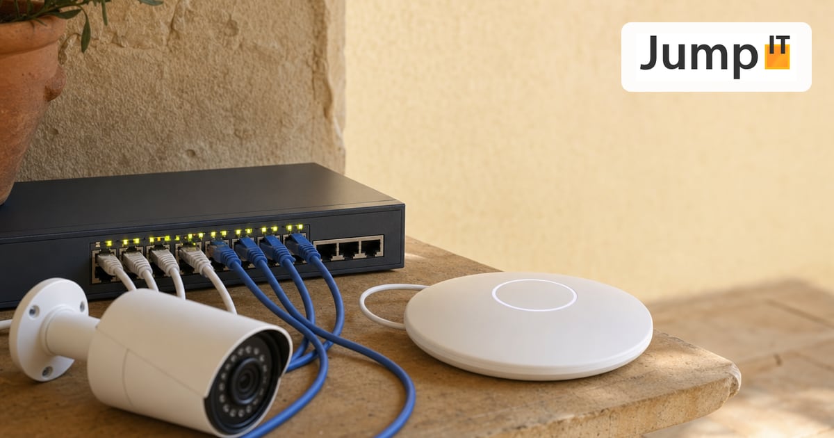
Imagine you’re mounting a new WiFi access point on the ceiling, at a spot where there is a network cable but no power outlet nearby. In the past that meant calling an electrician, pulling a cable and installing a socket. Today it means: plug in the cable, done.
That is what PoE (Power over Ethernet) does. It delivers power and data communication over the same network cable: no second cable, no power adapter, no outlet.
Part 1: PoE for Beginners
1. What is PoE in a nutshell?
PoE stands for Power over Ethernet: power delivered over the network cable.
A normal Ethernet cable has 8 wires (4 pairs). Depending on the speed, not all of them are needed for data transmission. PoE uses these wires twice: for data and for direct current.
The result: the device at the end of the cable (an access point, an IP camera, a VoIP phone) gets its network connection and its power at the same time. No power adapter, no second cable.
Analogy: imagine a water pipe that delivers hot water (power) and cold water (data) at the same time in a single pipe. At the device, the two are separated and each part is used where it’s needed.
2. Why is PoE so handy?
The answer lies in where the devices are mounted. Devices that use PoE almost always hang where there is no outlet:
- WiFi access points: on the ceiling, in the stairwell, in the attic
- IP security cameras: under the eaves, on the exterior wall
- VoIP phones: on the desk, with no outlet within reach
- Door intercoms & access systems: at the entrance
- Weather sensors, IoT devices: outdoors
Without PoE, each of these devices would need its own power adapter and its own outlet. With PoE, the network cable that has to be run anyway is enough.
Other advantages:
- Central power supply: the PoE switch sits in the distribution room on a UPS (uninterruptible power supply). If the power fails, all PoE devices keep running: cameras, access points, phones. With individual power adapters on the ceiling, that is almost impossible.
- Remote control: a PoE switch can switch individual ports off and on again by software, which is a “remote reboot” for the connected device. With a frozen access point: port off briefly, port back on. Done, no climbing a ladder.
- Fewer cables, less chaos: one infrastructure instead of two.
3. How does PoE work technically? Explained simply
Before a PoE switch sends power down a cable, it has a short detection dialog with the connected device:
- Searching: the switch sends a small test pulse to the port. It looks for a characteristic electrical signature: a resistance of about 25 kΩ. Only a genuinely PoE-capable device has this built in.
- Classifying: if the signature matches, the switch asks: “How much power do you need?” The device answers with its class (0-8). The class determines the power budget.
- Powering on: only now does the switch release the power, at the appropriate level.
- Monitoring: during operation, the switch constantly monitors power consumption. If a device suddenly draws far more power than agreed (e.g. a short circuit), the port shuts off immediately. This protects the cable, the switch and the device.
This handshake procedure is why PoE is safe: no blindly pushing power out, and no risk for devices without PoE support.
4. PoE standards: which ones are there?
This gets confusing quickly, because manufacturers use different terms. The most important points at a glance:
| Standard | IEEE standard | Max. power at the device | Typical devices |
|---|---|---|---|
| PoE | 802.3af (2003) | 12.95 W | VoIP phones, basic cameras |
| PoE+ | 802.3at (2009) | 25.5 W | WiFi access points, PTZ cameras |
| PoE++ (4-pair) | 802.3bt Type 3 (2018) | 51 W | High-end APs (WiFi 6/7), thin clients |
| PoE++ (4-pair) | 802.3bt Type 4 (2018) | 71.3 W | Industrial PCs, video conferencing systems |
The most important rule of thumb:
- Basic camera, VoIP phone → PoE (802.3af) is enough
- WiFi access point (almost all modern ones) → PoE+ (802.3at) at minimum
- UniFi U7 Pro, multi-radio APs, LiDAR devices → PoE++ (802.3bt) required
Backward compatibility: a PoE++ switch can also power PoE and PoE+ devices. Negotiating the power class happens automatically. It doesn’t work the other way around: a PoE switch (802.3af) can’t supply a PoE++ device with enough power.
5. What is a PoE switch?
A PoE switch is an ordinary switch that can also put power onto its ports. It is the heart of every PoE installation.
The most important figure is not the power per port, but the PoE budget: the total power the switch can distribute across all ports together.
Example: a switch has 8 ports at 30 W each (PoE+), which would be 240 W in theory. But the switch’s PoE budget is only 120 W. That means if all 8 ports draw their maximum at the same time, it isn’t enough. In practice no device constantly draws its maximum, but you need to keep an eye on the budget.
UniFi PoE switches show the current PoE consumption per port in real time in the controller, which is very handy for monitoring and planning.
6. What is passive PoE, and why is it dangerous?
Besides the IEEE standard there is passive PoE: a proprietary method found mainly with budget manufacturers and older Ubiquiti equipment.
The crucial difference: with passive PoE there is no detection handshake. The switch simply puts voltage on the port, whether or not the connected device supports PoE. That can damage or even destroy devices without PoE protection.
Passive PoE in practice:
- Older Ubiquiti devices (NanoStation, Rocket, airMAX) often use 24V passive PoE
- The voltage is fixed (usually 24V or 48V) and not negotiable
- Passive PoE injectors are cheap, but not compatible with IEEE-standard devices
The golden rule: never connect an IEEE 802.3af/at/bt PoE switch to a passive PoE device, or the other way around, without checking the specifications first. If in doubt: always ask us before devices get damaged.
Modern UniFi devices (since about 2015) use IEEE-standard PoE exclusively. Passive PoE is a phase-out model.
7. PoE injector: when the switch can’t do PoE
What if your existing switch has no PoE, but you want to power a single device (e.g. a camera) with it?
That’s what the PoE injector (also: PoE midspan) is for. It’s a small device with two RJ45 sockets:
- In: normal Ethernet from the switch
- Out: Ethernet + power to the device
The injector sits between the switch and the device and “injects” the power into the cable. Normal PoE Ethernet arrives at the device; it knows nothing about this.
Makes sense for: individual retrofits, when only one or two devices need PoE and replacing the switch would be disproportionate.
Doesn’t make sense for: more than two or three devices; then a PoE switch is the more economical and tidier solution.
8. PoE in UniFi: what you need to know
UniFi access points (U6 Lite, U6 Pro, U7 Pro, etc.) almost all rely on PoE: they have no power adapter. That isn’t a drawback but a design principle: the power supply belongs in the cabinet, not on the ceiling.
Typical UniFi requirements:
| UniFi device | Required PoE standard | Typical consumption |
|---|---|---|
| U6 Lite | PoE (802.3af) | ~6.5 W |
| U6 Pro | PoE+ (802.3at) | ~12.5 W |
| U7 Pro | PoE++ (802.3bt) | ~21 W |
| U7 Pro Max | PoE++ (802.3bt) | ~30 W |
| UniFi Protect cameras | PoE (802.3af) | ~8-12 W |
Important: the UniFi controller shows the current PoE consumption for every switch port. That is gold when planning: you can see immediately whether the switch’s PoE budget is sufficient, and you can prioritize ports.
Power cycle via the controller: if an access point freezes, one click in the controller → device → “Restart PoE port” is enough. That’s the remote reboot without a ladder.
Part 2: PoE for Professionals
The technical foundation for anyone who wants to know the details.
9. The IEEE 802.3bt standard in detail: how power flows over wires
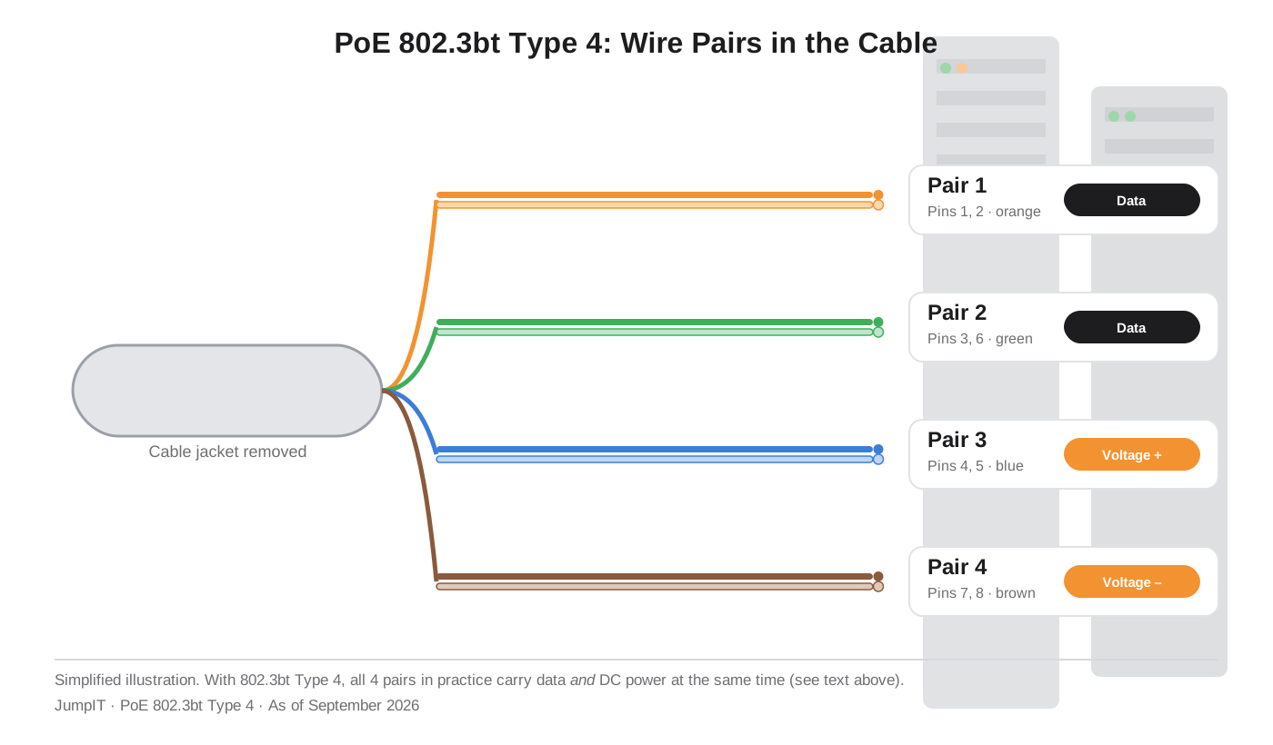
A Cat5e/Cat6 cable has 8 wires, divided into 4 twisted pairs:
- Pair 1: pins 1, 2 (orange)
- Pair 2: pins 3, 6 (green)
- Pair 3: pins 4, 5 (blue)
- Pair 4: pins 7, 8 (brown)
For PoE (802.3af/at) there are two methods of transmitting power:
Mode A (Alternative A): power flows over the data pairs (pins 1/2 and 3/6). Positive on one pair, negative on the other. The data signals ride on top as high-frequency signals; they don’t interfere with each other because data signals are AC signals and the power is DC.
Mode B (Alternative B): power flows over the unused pairs (pins 4/5 and 7/8), which aren’t needed for data on 100 Mbit/s connections.
With PoE++ (802.3bt), all 4 pairs are used, both for data (at Gigabit/10G) and for power. That doubles the transmittable power to up to 71.3 W at the device (90 W at the switch port; the rest is lost as heat in the cable).
Cable losses: the cable itself has resistance. With long cable runs (near the 100 m limit) and high power demand, the voltage drop can be considerable. An 802.3bt device that needs 50 W might only get about 43 W at the device over 100 m of Cat5e; you have to factor that in when planning.
Rule of thumb for cable losses: per 100 m of cable and 1 A of current, you lose approx. 9 V with Cat5e. With Cat6a the loss is lower.
10. PoE classes (power classes): the language of negotiation
The power class is negotiated between the switch and the device in two stages:
Stage 1: physical classification (resistance) The device has a resistance between the detection pins. The switch measures this resistance and infers the class.
Stage 2: LLDP negotiation (Layer 2) Modern devices use the LLDP protocol (Link Layer Discovery Protocol) to communicate their exact power requirements digitally. This is more precise than the physical class and allows fine-grained budget planning.
| Class | Max. power at device | Max. power at switch port | Standard |
|---|---|---|---|
| 0 | 12.95 W | 15.4 W | 802.3af |
| 1 | 3.84 W | 4.0 W | 802.3af |
| 2 | 6.49 W | 7.0 W | 802.3af |
| 3 | 12.95 W | 15.4 W | 802.3af |
| 4 | 25.5 W | 30.0 W | 802.3at |
| 5 | 40 W | 45 W | 802.3bt Type 3 |
| 6 | 51 W | 60 W | 802.3bt Type 3 |
| 7 | 62 W | 75 W | 802.3bt Type 4 |
| 8 | 71.3 W | 90 W | 802.3bt Type 4 |
The difference between “switch port” and “device” is the cable loss, which the IEEE standard already anticipates in its planning.
11. PoE budget planning: how to calculate it correctly
A switch’s PoE budget is the maximum total power it can deliver to all PoE ports together. It is not the same as the sum of all port maximums.
Example calculation for a typical finca installation:
| Device | Quantity | Consumption (typical) | Total |
|---|---|---|---|
| UniFi U6 Pro (AP) | 3 | 12.5 W | 37.5 W |
| UniFi U7 Pro (AP) | 1 | 21 W | 21 W |
| UniFi G4 Dome camera | 4 | 8 W | 32 W |
| VoIP phone | 2 | 5 W | 10 W |
| Total | 100.5 W |
Recommendation: plan for a 20-30% buffer → choose a switch with at least 130 W PoE budget.
Why a buffer? Devices briefly draw more power at startup than during operation (inrush current). Also, future expansions can use up the budget quickly.
UniFi switches with a good PoE budget:
- USW-24-PoE: 95 W budget
- USW-48-PoE: 195 W budget
- USW-Pro-24-PoE: 400 W budget
- USW-Pro-48-PoE: 600 W budget
12. PoE and cable quality: why the cable suddenly matters
With data-only cables, quality from Cat5e upward is sufficient for most applications. With PoE, especially PoE++, a new dimension comes in: heat generation.
Current through a resistance generates heat (P = I² × R). With 802.3bt at up to 1.7 A per pair and long cable runs, this can lead to real temperature problems in poorly ventilated cable ducts with many tightly bundled cables.
The IEC 60512-99-001 standard deals with exactly this: it defines how bundled PoE cables dissipate heat and when a derating table applies for the maximum cable length.
Practical consequences:
- With PoE++ (802.3bt): prefer Cat6a over Cat5e: lower resistance, less heat, less voltage drop
- Don’t bundle cables extremely tightly in the duct; air circulation is needed to dissipate heat
- With very long runs (>70 m) and high power: measure the voltage at the device instead of just estimating it
13. PoE troubleshooting: the checklist
When a PoE device gets no power or behaves strangely:
First check: port status in the UniFi controller:
- Does the port show “PoE active”? If not → see below
- What power consumption does the port show? (0 W = no device detected)
- Is PoE enabled on the port? (Settings → Devices → Switch → Ports → PoE Mode)
Cable and connectors:
- Cable shorter than 100 m?
- Are all 4 wire pairs correctly terminated (not a cheap 4-wire cable)?
- Connectors crimped cleanly? Bad crimps increase resistance → PoE detection fails
Power budget:
- Is the switch’s PoE budget exhausted? (UniFi shows total consumption)
- Does the port have the right PoE class set? (Auto or manually limited?)
Device:
- Does the device really support IEEE PoE (not just passive PoE)?
- Does the device need PoE+ or PoE++, but is running on a PoE port?
- Does the device work with a directly connected PoE injector? → Yes = switch problem, No = device problem
Quick test:
In the UniFi controller:
Devices → Switch → select port → "Power Cycle PoE"

Or via SSH on the switch (USW):
swctrl poe show      # Shows PoE status of all ports
swctrl poe show port X  # Details for port X
14. Summary: PoE at a glance
| Feature | PoE (802.3af) | PoE+ (802.3at) | PoE++ (802.3bt) |
|---|---|---|---|
| Year | 2003 | 2009 | 2018 |
| Max. power (device) | 12.95 W | 25.5 W | 51 / 71.3 W |
| Pairs used | 2 (Mode A or B) | 2 (Mode A or B) | 4 (all pairs) |
| Typical devices | VoIP, basic cameras | Access points, PTZ cameras | High-end APs, thin clients |
| UniFi relevance | U6 Lite, cameras | U6 Pro, U6 Mesh | U7 Pro, U7 Pro Max |
More articles
 Networks Retrofitting Network Cable: Is It Worth It?
Pros and cons of retrofitting network cable, the realistic effort, and how we find existing conduits with the Kati® Blitz Ortung 2.0 without opening the wall.
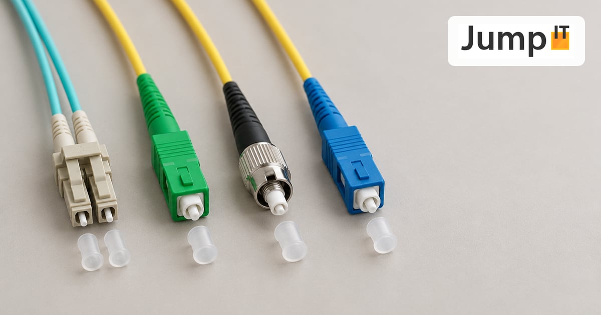 Networks Fiber Types: OM1 to OM5, OS1/OS2, G.652.D and G.657
Multimode or singlemode? OM1 to OM5, OS1 and OS2, G.652.D and the bend-insensitive G.657.A1/A2 explained, with ranges, colors and an overview of SC, LC, FC, ST, E2000 and MPO connectors.
 Networks Fiber Optic Color Codes: Fiber Order Explained Simply
Red, green, blue or blue, orange, green? DIN/IEC 60304 vs. TIA-598 color codes, counting from fiber 13, loose tubes and connector colors, with tips for splicing and patching.
 Networks GPON and XGS-PON: What’s Behind Your Fiber Connection?
GPON or XGS-PON? How both fiber technologies work, what 1 and 10 Gbit/s really bring, which providers in Spain use what and where things stand on Mallorca.
Note: images and parts of the text on this page were created with the help of artificial intelligence and editorially reviewed by JumpIT.
← To the knowledge center